All Activity
- Last week
-
 The 10th World Battery & Energy Storage Industry Expo (WBE 2025) Date: August 8th-10th, 2025 Venue: Area of China Import and Export Fair Complex, Guangzhou Address: No.380, Yuejiang Zhong Road, Guangzhou, China Website:http://en.battery-expo.com/ Review of WBE 2024 Held from August 8th to 10th in Guangzhou, WBE 2024 spanned 100,000 sq.m, and featured 1,205 exhibiting companies from 14 countries (Including 476 cells, packs & energy storage exhibitors), hosting notable names like BYD, EVE, Great Power, GOTION HIGH-TECH, Tianneng, Pisen, EAST Group, Ganfeng Lithium, HiNa Battery, Transimage Sodium-lon Battery, Roofer Group, Super Flower, Dejin New Energy, Joysun Energy, Haidi Energy, Horizontal Na Energy, LongTTech, Highstar, Horizon New Energy, Huamingsheng Tech, Han's SLE, HONBRO, AirTAC, etc. The event drew in 175,492 professional visits, representing a 27.63% growth compared to last year, including 10,586 overseas visits from over 150 countries and regions. Preview of WBE 2025 WBE 2025 is set to take place from August 8th to 10th at the China Import and Export Fair Complex to showcase the rapid growth of the battery and energy storage industry. With a larger scale than ever, the event will cover 165,000 sq.m and host over 2,000 exhibitors in 6,000 booths with an expected turnout of 200,000 visits. In addition, WBE 2025 will again be held alongside the Solar & PV expo and the World Hydrogen Energy Industry Expo (WHE), highlighting the synergy between different renewable energy sectors. Live Events & Activities of WBE 2025 The 3rd China Battery and Energy Storage Industry International Trade Forum 2025 2025 China Energy Storage Industry Ecosystem Conference 2025 China Battery Industry (Guangzhou) Summit 2025 World Hydrogen Energy Industry Conference 2025 Energy Storage Industry International Exchange Dinner 2025 International Buyers Matchmaking Meeting The 3rd WBE Factory Tour 2025 Exhibitor Profile Battery Technology Lithium Batteries/ Lead-acid Batteries/ Solid-state Batteries/ Fuel Cells/ Flow Batterie Energy Storage Systems and Solutions Residential Energy Storage Systems/ Commercial Energy Storage Systems/ Industrial Energy Storage Systems/ Grid-scale Energy Storage Systems Battery Management Systems (BMS) Battery Monitoring Systems/ Battery Protection Systems/ Thermal Management Systems Energy Storage Inverters DC/AC Inverters/ Bidirectional Inverters Energy Storage Materials Cathode Materials/ Anode Materials/ Electrolytes/ Separators Supercapacitors High Energy Density Capacitors/ High Power Density Capacitors Hydrogen Energy and Storage Technology Hydrogen Storage Tanks/ Hydrogen Fuel Cells/ Hydrogen Production Equipment Renewable Energy Integration and Smart Grid Technology PV Energy Storage Systems/ Wind Energy Storage Systems/ Microgrids Power Batteries and Applications EV Batteries/ Energy Storage Battery Packs/ Power Tool Batteries Production Equipment, Testing Device and Solutions Battery & Energy Storage Production Equipment/ Battery & Energy Storage Testing Equipment/ Reliability and Safety Testing/ Life Cycle Testing Equipment If you are interested in exhibiting or visiting, please let us know through the given contact below! Guangzhou Honest Exhibition Co., Ltd Guangdong Energy Storage Industry Association Contact Person: Natalia Zeng Mobile/Wechat/: +86 18565156106 Whataspp: +86 15217093652 E-Mail: NataliaWBE@163.com Address: Shenghui Building, No. 1095, Zhongshan Middle Avenue, Tianhe District, Guangzhou, China
 -
Natalia-2025 joined the community
-
 msonmaarleyo9495 joined the community
 - Earlier
-
 spartasun joined the community
 -
.thumb.png.7df20be78fe855315cef0993a4f2ab8c.png) Kingrole changed their profile photo
Kingrole changed their profile photo -
Difference between 1N4148, 1N4007, 1N5819
Kingrole replied to Bob Collin's topic in Electronic Components
Difference Between 1N4148, 1N4007, and 1N5819 Diodes When it comes to selecting the right diode for your electronic circuit, understanding the differences between commonly used diodes is essential. In this article, we will compare three popular diodes: the 1N4148, 1N4007, and 1N5819. Each of these diodes has unique characteristics that make them suitable for different applications. 1. Introduction to the Diodes 1N4148: This is a high-speed switching diode designed for applications requiring fast switching speeds and low capacitance. It is commonly used in RF circuits, digital logic, and protection circuits. 1N4007: A rectifier diode with high current and voltage ratings, making it ideal for power supplies and rectification in high-voltage applications. 1N5819: A Schottky diode known for its low forward voltage drop and fast recovery time, suitable for high-frequency applications and rectification in low-voltage circuits. 2. Technical Specifications Maximum Reverse Voltage (VR): 1N4148: Typically rated for up to 100V. 1N4007: Rated for up to 1000V. 1N5819: Generally rated for around 40V. Forward Current (IF): 1N4148: Can handle currents up to approximately 200mA. 1N4007: Can handle currents up to 1A. 1N5819: Has a forward current rating of about 3A. Reverse Recovery Time (trr): 1N4148: Offers relatively fast reverse recovery times. 1N4007: Has a longer reverse recovery time compared to the 1N4148. 1N5819: Known for extremely fast reverse recovery, minimizing switching losses. Forward Voltage Drop (VF): 1N4148: Approximately 0.7V at room temperature. 1N4007: Around 1.1V at room temperature. 1N5819: Lower than typical silicon diodes, around 0.3V to 0.4V at room temperature. 3. Application Suitability 1N4148: Ideal for high-frequency switching applications, RF circuits, and protection against overvoltage. 1N4007: Suitable for rectifying AC to DC in power supplies, especially those requiring high current and voltage handling. 1N5819: Best for applications requiring low forward voltage drops, such as in solar cells or as a freewheeling diode in motor control circuits. 4. Conclusion Choosing the correct diode depends on the specific requirements of your circuit. For high-frequency switching applications, the 1N4148 is a good choice. For power supply rectification and high current handling, the 1N4007 is preferred. When low forward voltage drop and fast switching are critical, the 1N5819 is an excellent option. Additional Information: If you have any technical questions or require solutions for (1N4148, 1N4007, 1N5819) or other products, please feel free to visit our official website at www.kingrole.com.cn to leave a message. We are dedicated to addressing all your product-related technical inquiries and providing professional electronic component solutions. We look forward to the opportunity of working with you in the future! -
JRC4558 vs TL072: What are Differences
Kingrole replied to erintse01's topic in Electronic Components
When it comes to selecting the right operational amplifier (op-amp) for different applications, engineers often weigh various models against each other. This article will explore the differences between the JRC4558 and TL072, helping you better understand their individual characteristics and how to choose the best component for your project. 1. Performance Overview JRC4558: A dual operational amplifier known for its performance in audio applications. It features low noise levels, making it ideal for instrument preamplifiers, mixers, and other high-quality sound equipment. TL072: Also a dual operational amplifier, but more commonly used in general applications due to its faster slew rate and lower input bias current, which makes it suitable for applications requiring fast response and low power consumption. 2. Technical Specifications Comparison Gain Bandwidth Product (GBW): The TL072 has a higher gain bandwidth product, meaning it can handle signal amplification at higher frequencies. Power Supply Voltage Range: Both models can operate within a wide range of supply voltages, though the specific values may vary. Input Bias Current (Ib): The TL072 typically has a lower input bias current than the JRC4558, making it more appropriate for applications that require high precision. Noise: The JRC4558 is renowned for its low noise level, which is crucial for audio applications. 3. Application Scenarios JRC4558: Its low noise characteristics and excellent audio performance make it well-suited for audio equipment and music production devices. TL072: Its fast slew rate makes it applicable for high-speed data acquisition systems and other applications requiring rapid signal processing. 4. Conclusion Choosing between the JRC4558 and TL072 depends on your specific requirements. If you're looking for a low-noise op-amp suitable for audio applications, the JRC4558 might be the better choice. Conversely, if you need an op-amp with a fast slew rate and low input bias current, then the TL072 would be more appropriate. Additional Information: If you have any technical questions or require solutions regarding the JRC4558, TL072, or any other products, please feel free to visit our official website at www.kingrole.com.cn to leave a message. Our team is dedicated to addressing all your product-related technical inquiries and providing professional electronic component solutions. We look forward to the opportunity of working with you! -
The Murata GRM21BR71C475KA73L is a high-reliability multilayer ceramic capacitor (MLCC) designed for use in a variety of electronic circuits where stability and reliability are paramount. This component belongs to Murata's lineup of surface-mount MLCCs that are known for their robust performance across different operating conditions. Key Features and Applications : Capacity and Tolerance: The GRM21BR71C475KA73L has a capacitance value of 475 pF with a tolerance of ±10%, making it suitable for applications that require precise capacitance values. Voltage Rating: With a rated voltage of 100V, this capacitor is ideal for circuits that operate within this voltage range. Temperature Coefficient: It features a temperature coefficient of X7R (E24), which means its capacitance varies by ±15% over a temperature range of -55°C to +125°C. This makes it suitable for environments where temperature fluctuations are expected. Size and Package: The compact size (0603 metric, 0201 inch) allows for dense PCB layouts, which is essential for miniaturized electronics. Reliability: Known for its high reliability, the GRM21BR71C475KA73L meets rigorous standards for durability and performance, making it a trusted choice in automotive, industrial, and consumer electronics applications. Usage and Benefits Signal Coupling and Decoupling: In power supply circuits, the GRM21BR71C475KA73L can be used for decoupling to reduce voltage ripple and noise, ensuring a clean power supply to sensitive components. Noise Suppression: Its excellent frequency characteristics make it effective in suppressing high-frequency noise, enhancing the overall signal integrity in high-speed digital circuits. Timing Circuits: In timing and oscillation circuits, the precise capacitance and stable performance contribute to accurate timing signals. Energy Storage: For applications requiring energy storage, the GRM21BR71C475KA73L provides reliable charge retention and discharge capabilities. Additional Information : For more detailed technical specifications and application notes, you can refer to the datasheet provided by Murata. If you have any questions regarding the GRM21BR71C475KA73L or other electronic components, feel free to visit our official website at www.kingrole.com.cn and leave a message. Our team will be happy to assist you with any product-related inquiries and offer tailored solutions to meet your specific needs. We look forward to the opportunity to collaborate with you!
-
What is the CC1000-RTB1 Transceiver used for ?
Kingrole replied to KAKU's topic in Electronic Components
The CC1000-RTB1 is a transceiver module based on the CC1000 RF chip, widely used in short-range wireless communication applications. This module features integrated RF front-end and baseband processing capabilities, supporting multiple wireless communication protocols such as IEEE 802.15.4, Zigbee, and WirelessHART. Below is an explanation of each component in the block diagram: LNA (Low Noise Amplifier): The LNA at the receiver end provides gain, reduces the noise figure, and enhances the receiver sensitivity. MIXER: The mixer converts the received RF signal to an intermediate frequency (IF) signal for further processing. IF Stage: This stage filters and amplifies the IF signal, removing unwanted spurious signals. DEMOD (Demodulator): It demodulates the IF signal into digital data, extracting the original information. VCO (Voltage Controlled Oscillator): Provides a variable frequency local oscillator signal that mixes with the external signal to generate new frequencies. Charge Pump: Adjusts the VCO frequency for phase-locked loop (PLL) frequency control. PD (Photodiode): Used to detect the power level of the VCO output, providing feedback to the PLL for closed-loop control. LPF (Low Pass Filter): Filters out high-frequency components to smooth the output signal. PA (Power Amplifier): At the transmitter end, the PA supplies sufficient power to meet transmission requirements. BIAS (Bias Circuit): Provides the necessary voltage and current to ensure proper operation of all components. OSCs (Oscillators): Generate stable clock signals for data sampling and processing. The CC1000-RTB1 Has The Following Features: Flexible Modulation Schemes: Supports GFSK, MSK, OOK, and FSK among other modulation methods. Low Power Consumption: Utilizes CMOS technology, resulting in low power consumption suitable for battery-powered devices. High Integration: Integrates most RF and baseband functions, simplifying hardware design. Strong Interference Resistance: Possesses certain interference resistance and error correction capabilities, ensuring communication quality. With the CC1000-RTB1, developers can rapidly build wireless communication systems for applications in smart homes, industrial automation, healthcare, and more. Additional Information: If you have any technical questions about the CC1000-RTB1 or other products, or need solutions, please visit our official website at www.kingrole.com.cn to leave a message. We will answer your product-related technical questions and provide you with professional solutions. Looking forward to the opportunity to cooperate with you in the future! -
Are there different BD140 transistor pinouts?
Kingrole replied to bitfoic's topic in Electronic Components
Hello, Bitfoic! The BD140 is a common NPN silicon transistor that is widely used in various electronic circuits such as amplifiers and switching applications. Transistor pin configurations typically follow certain standards, but different manufacturers may use varying packaging methods. For the BD140, it usually has three pins corresponding to the Emitter (E), Base (B), and Collector (C). In A Typical To-92 Package, The Pinout Of The Bd140 Is As Follows: From the bottom view, from left to right: Emitter (E), Base (B), Collector (C). Looking from the top with the marking side facing you, the first pin on the left is the Emitter (E), the middle pin is the Base (B), and the rightmost pin is the Collector (C). However, different manufacturers might have different packaging, so if the pin configuration of the BD140 you encounter seems different from the above description, it's best to consult the specific manufacturer’s datasheet or specifications to confirm the pin functions. Additional Information: If you have any technical questions or require solutions for BD140 transistor or other products, please feel free to visit our official website at www.kingrole.com.cn to leave a message. We are dedicated to addressing all your product-related technical inquiries and providing professional electronic component solutions. We look forward to the opportunity of working with you in the future! -
 PatriarchB joined the community
 -
 peachapple joined the community
 -
Dear Community Members,
We are thrilled to announce that Kingrole, a professional electronics components trading company, has recently joined the Electronics Forums community! Since our establishment in Shenzhen back in 2005, we have been dedicated to supplying high-quality electronic components such as ICs, modules, transistors, and passive components. Our products find applications across a wide range of industries including industrial automation, telecommunications, new energy, and automotive electronics.
At Kingrole, we take pride in offering both standardized products and custom solutions, ensuring that every requirement is met with precision and excellence. By partnering with leading manufacturers globally, we guarantee that each component we provide is of top-notch quality and reliability.
We look forward to connecting with professionals and enthusiasts on this platform to share our expertise and learn from the wealth of knowledge within this community. Whether you have questions about specific components, need advice on solutions, or simply wish to discuss the latest trends in the electronics industry, we will be here to engage and support.
Join us as we explore the endless possibilities within the electronics industry. Every collaboration is a significant step forward, not only fostering technological advancement but also propelling us collectively towards a brighter future in electronics.
Best regards, The Kingrole Team
-
 pencilpen joined the community
 -
 ahleyusasdoz1105 joined the community
 -
 Raymondbuh joined the community
 -
 zvictoriafranesz9743 joined the community
 -
Kingrole joined the community
-
I am having difficulty connecting the ST-LINK/V2 clone to my microcontroller. An error appears in the ST-LINK utility. I have already verified all the connections, including the decoupling capacitor, all the pin connections, power supply connections, and USB drivers, but I am still unable to resolve the error. Here, I have attached my connections with ST-LINK pin numbers. Can anyone please help me solve this error?


-
Thank you so much I where yellow and green off thinking and searching
-
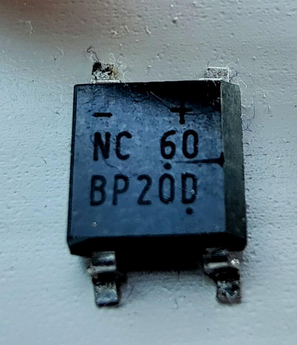
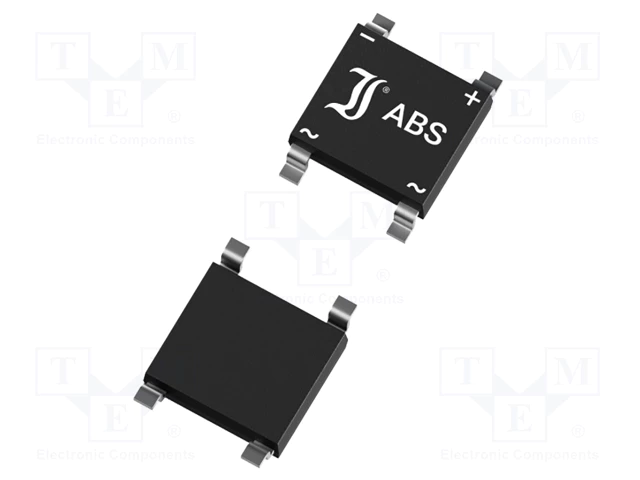
This is a rectifier bridge. You can replace it with ABS20D 2A bridge.
-
I got this component and I search high and love Now i found my self in the field of the great God Can anyone help me what this is

-
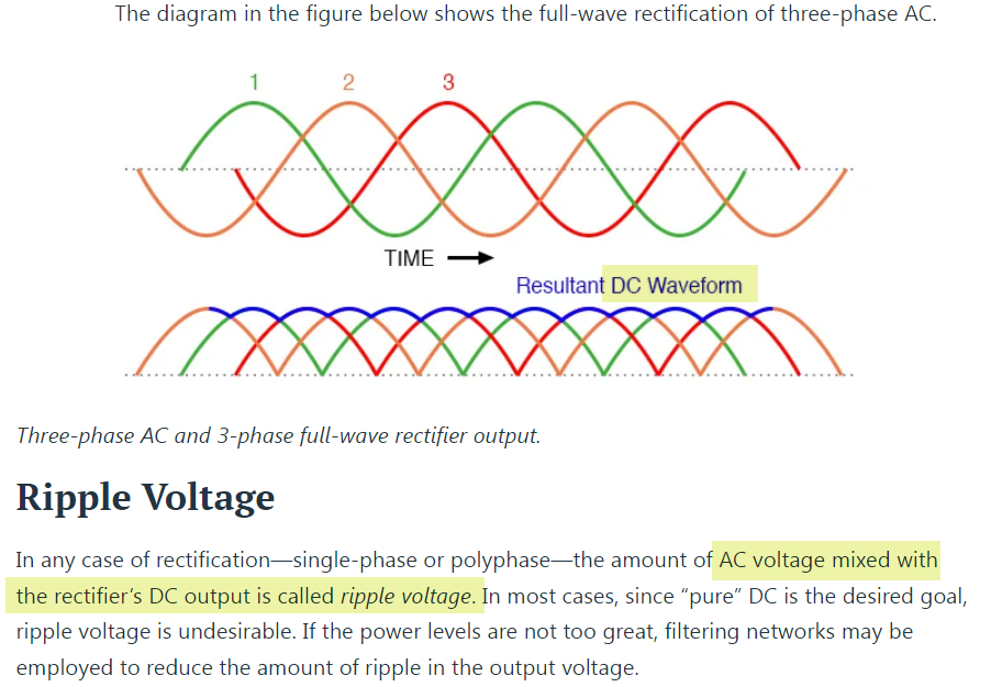
The alternator ripple refers to the fluctuation in the output voltage produced by an alternator. It is caused by variations in the magnetic field within the alternator's stator winding. Excessive ripple can lead to electrical system instability and potential damage to electronic components. Proper maintenance and monitoring are essential to ensure the alternator operates within acceptable limits and provides stable power output.
-
Is alternator ripple pulsating DC or is there a bit of AC mixed in? Diagram from another site seems to be offering contrary information.
-
Can Google Assistant really be trusted to control our home appliances, or is it just another invasion of privacy waiting to happen? Are there any security risks involved in integrating smart devices with voice-controlled assistants like Google Assistant?
-
In an audio application that requires high fidelity, such as a mixing console in a professional recording studio, how would you weigh the choice between the JRC4558 and the TL072 op amps? Considering factors such as sound quality, noise level, and input impedance, how would you decide which op amp is better suited for a specific audio processing need? Here's the related article about JRC4558 vs TL072: https://www.avaq.com/technology/jrc4558-vs-tl072-what-are-differences-and-how-to-choose Thanks.
-
where's the pic?
-
In electronic manufacturing industry, PCB and PCBA are two terms that are often used interchangeably, but they actually refer to different aspects of the manufacturing process. Understanding the difference is essential for anyone involved in the electronics industry. Let’s delve deeper the difference between PCB and PCBA. Regarding PCB Printed Circuit Board (PCB) is the foundation of any electronic device. It is a flat board made of non-conductive material, usually fiberglass, with conductive pathways etched or printed onto it. These pathways, known as traces, form the circuitry that connects the various electronic components on the board. PCBs come in different shapes, sizes, and complexity levels depending on the specific application.The following characteristics summarize the distinct features of a PCB: High wiring density coupled with small size and lightweight properties contributes to the miniaturization of electronic devices. As graphics can be replicated consistently on each board, errors in wiring and assembly are minimized while saving time during equipment maintenance, debugging, and inspections. The utilization of mechanized and automated production is beneficial, as it enhances labor productivity and decreases the expenses associated with electronic equipment. Standardizing the design allows for easier interchangeability, which is advantageous in various industries. Regarding PCBA PCBA stands for Printed Circuit Board Assembly.It refers to the complete process of assembling PCB empty boards using SMT followed by DIP plugins. SMT (Surface Mounted Technology) is a method of mounting micro and small parts onto a PCB board without the need for drilling holes. It involves positioning the PCB board, printing solder paste, using a mounting machine for component placement, reflow soldering in a furnace, and conducting production inspections. On the other hand, DIP or “plug-in” is the process of inserting larger parts into pre-drilled holes on a PCB board. These parts are not suitable for SMT technology and are integrated by plugging them in. The production process for DIP includes applying adhesive, plugging in the components, performing inspections, wave soldering, plate brushing, and conducting production inspections. Both SMT and DIP play crucial roles in assembling PCBs with different types of components. While SMT focuses on surface-mounted technology without drilling holes on the board itself, DIP involves inserting larger parts into pre-made holes to ensure proper integration. In summary PCBA encompasses both SMT assembly as well as plug-in assembly techniques to create fully functional printed circuit boards with various electronic components. PCB vs PCBA: Understanding the Difference Based on the introduction provided, it is evident that PCBA typically denotes a manufacturing process and can also be interpreted as a completed circuit board. The calculation of PCBA can only occur once all the procedures on the PCB board have been finalized. On the other hand, a PCB refers to an empty printed circuit board without any components attached. In summary, PCBA represents a finished board while PCB signifies an unpopulated one. Fuxin PCB vs PCBA service Fuxin specializes in Contract Manufacturing of Electronic Products, from prototypes to small & medium production volumes of PCB Assembly & Turnkey assembly/ box build. Our one-stop PCBA/OEM service support multiple markets, including industrial,medical,communications network, automotive,multimaedia,consumer electronics,clean technology and oil&gas.
-
I’m wanting to replace my burnt up transformer out of my soldering station. It has two separate transformers for the soldering iron and the Desoldering. Both transformers have an input of 115v. Output of 0-12v-0-25v, but the one for the Desoldering has secondary output of 0-7v-0-24v. the part number comes up but the part is no longer available. I’m still sort of new to this stuff, I wouldn’t care to replace both of the transformers if I had to. thanks Here’s pictures of the one
-

Difference between 1N4148, 1N4007, 1N5819
hskdnfnfamjsxnk replied to Bob Collin's topic in Electronic Components
Hi Bob, I am sharing the part about 1N4148. Thanks. -
Hello all, I’m fairly new to electronics and I know the basics but I’ve always been intrigued. Well I’ve been wanting to build my own spot welder for lithium batteries to fix my power tool batteries. I plan on using the transformer out of a microwave, now the part I’m confused about is the relay timer. How can I go about doing that and wiring it up? Also could I use the board from a microwave being it has the relay and the timer already built in? another thing I’m curious about is I have an old Tenma soldering station which inside has 2 transformers which are small. Is there anyway I could use it and just reverse certain things? thanks
-
OP27G is Instrumentational OP Amps
-
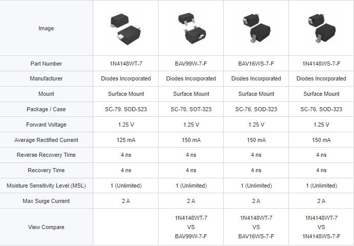
The three parts on the right have similar specifications to Diodes Incorporated & 1N4148WT-7.
-

Difference between 1N4148, 1N4007, 1N5819
lostintheethes replied to Bob Collin's topic in Electronic Components
more information about 1N4148 -
Hello everyone, I have a question that I would like to share with you: I am currently working on a project where I want to share the input PAD of an ADC with the GPIO's PAD. The main purpose behind this is to save costs. The GPIO PAD supports 5V tolerance, while the ADC only allows a maximum input voltage of 3.6V. I have implemented a switch (transmission gate) between the ADC and the PAD, which allows me to turn off the ADC when it is not in use. However, I have a concern regarding the situation where the PAD voltage is 5V, as it could potentially conduct through the PMOS of the switch and damage the ADC. Could someone please guide me on how to address this issue? Thank you all for your assistance. Best regards, Fred
-

Difference between 1N4148, 1N4007, 1N5819
Xavier John replied to Bob Collin's topic in Electronic Components
Hi, I find lots of IN4007 here. Wish you like it