


admin
-
Posts
18 -
Joined
-
Last visited
-
Days Won
2
About admin

admin's Achievements
")


-
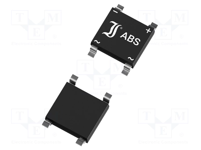
This is a rectifier bridge. You can replace it with ABS20D 2A bridge.
-
This seems to be a Multilayer Ceramic Capacitor MLCC 4.7 uF 16 VDC size 0805 https://gr.mouser.com/datasheet/2/281/GCM21BR71C475KA73_01-1968756.pdf Is this what you are looking for ?
- 1 reply
-
- 1
-

-
It's because it's partially depleted or possible damaged.
-
Could you post a schematic to make this more clear ?
-
This is an OPAMP - Operation Amplifier and can be used in various circuits. Do you have any schematic of board view ?
-
Could you show us a photo ?
-
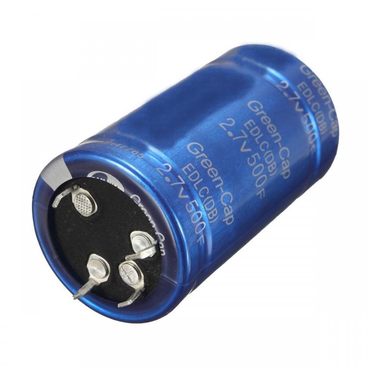
It seems that your cap has 4 pins on the bottom, two of them are the actual capacitor terminals and the other two are for mechanical stability and not play any electric role. Check the attachment. You can also notice that there are no tracks going to these pins, so it's OK not to be soldered.
-
Seems something is shorted here. Could you post your actual schematic to identify the issue ?
-
One way to determinate the voltage of capacitor is to check the datasheet of LM1117. According to the datasheet this capacitor is placed on the input of voltage regulator, so what is the maximum expected input voltage to the regulator? If it's 12V then a 16V capacitor should be enough. Also 16K indicates the rated voltage and tolerance of capacitor. So this is clearly a 16V capacitor with +/-10% tolerance in capacitance.
-
Hi Richard, Welcome to our community. We are glad you are on-board. Feel free to start a new topic as per your needs. Mike
-
smart security system nd Bluetooth base home automation
admin replied to denish limbachiya's topic in Electronic Projects
Which Bluetooth module do you want to use for your home automation project? -
Are you representing a LED company? or what the purpose of you message.
-
Welcome emc2. Feel free to share your circuits and toughts with our community.
-
PCB problems should be noticed in the design
admin replied to a topic in General Electronic Discussion
In addition i attach here the Sparkfun rules when designing a PCB. Following these rules you may avoid basic issues when designing a new PCB. Hope it's helpfull. SparkFun rules.pdf -
Your best friend is the IC datasheet. Take a look at page 11 where you will find an Application diagram. This is your first step to understand how this IC can be used in your application. I don't think you can find a such specific tutorial over the internet.

