

minhrung
-
Posts
17 -
Joined
-
Last visited
-
Days Won
1
Recent Profile Visitors
5,259 profile views


minhrung's Achievements
")
Newbie (1/14)
1
Reputation
-
The keyboard also known as the keypad is fairly common use in programming the microcontroller to enter data quickly. Currently, there are different kinds keypad, but the most common are type 3 × 4 and 4 × 4. To identify an action occurs on the keypad, we implement continuous keypad scan to detect it. Compiler mikroC Pro for Pic has supported us a library of functions to perform a simple scan most keypad. Library in mikroC compiler function keypad (Keypad Library): Keypad_Init (): Before you use the other functions of the library keypad, you must call this function before. Keypad_Key_Press (): Read from the keyboard keys are pressed, if no key is pressed, the function returns 0. Keypad_Key_Click (): The function will wait until the first key pressed and released. When the key is released, the function returns a value from 1 to 16, depending on the keys on the keypad. If more than one key is pressed, the function will wait until the key is released. Then, the function returns the value of the first key is pressed. Video: https://www.youtube.com/watch?v=eOZ4e0jM-LQ Code mikroC and proteus file here
-
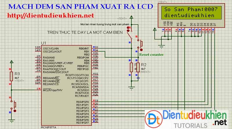
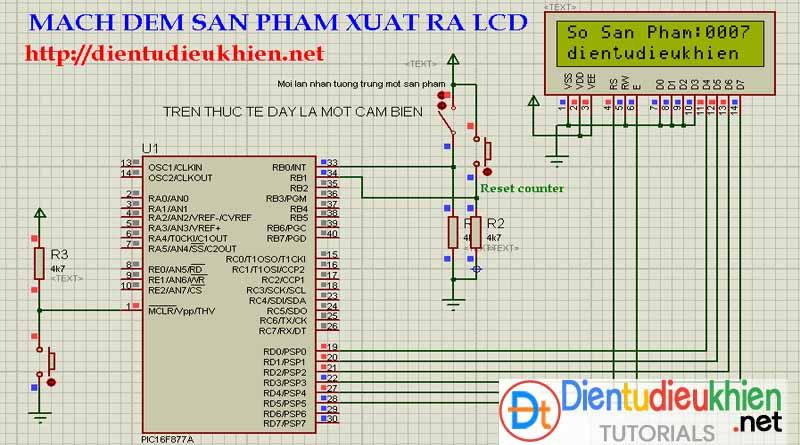
This is a project to simulate a system product count on the belt, a sensor system (here you can use infrared and optical sensor pair back to this, or buy other specialized modules) used to detect a product, whenever products run through the counter will increase by one unit, the results are displayed on the LCD screen. You may also be replaced by the 7-segment LED LCD to display the results, to do this you need to see how to scan and programmable 7-segment LED display 7-segment LED on pic 16f877a microcontroller. Download code and simulation
-
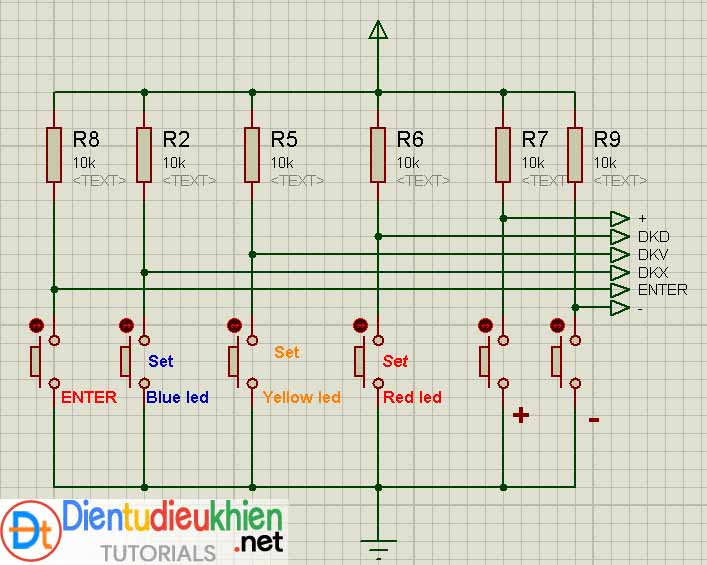
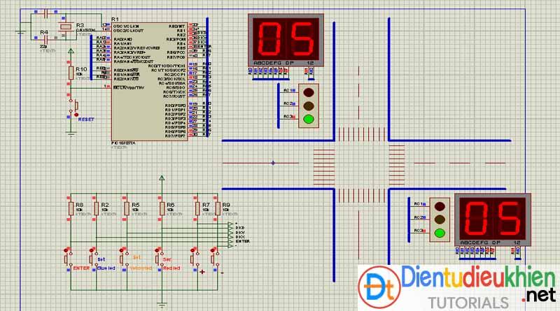
In previous versions Traffic light project can only function control LEDs and display count, can not set a time for each to be led by hand. In this version, we absolutely can set the time for the system via the button lights easily. To understand this project faster, you can review the following basic project: Treatment Project button buttons7 segment display and programmable 7-segment LED scanScan 2 7-segment LED on the pic 16f877aBasically this project like project "Simulation of traffic lights - Traffic light", but here there is a system update installed part time. Which means that, you absolutely can set the time for the easily led system through push buttons. Button (+): increase 1 function unit (number).Button (-): function reduction unit (s)Set Red Led: when you use the button (+), (-) to select the time and use this button to set the time for the red LED.Set Yellow Led: set time for yellow LED.Set Blue Led: set time for yellow LED.Enter: the completion of the set time for the LED, press the Enter key to system operation.When you want to reset the parameters when pressing button (Reset), at which the program will start from scratch and you can reinstall the time. || code C and simulation proteus file

-
For those of you new to the board Arduino Arduino uno Rv3 is the most appropriate, it is very simple and low cost. Put simply, but enough so that you programmed a lot of things ... Here is a book by author John Boxall very detailed instructions from the Arduino Uno Rv3 familiar with, from the installation guide and get acquainted arduino ide program, the structure of a program, and 65 specific examples. When you read and work through the exercises in this book, I guarantee you will be well informed about basic arduino uno. Arduino workshop - dientudieukhien.net|| Download ebook here
-
Protues is a pretty robust program to simulate an electronics project, it is stronger in the simulation for the microcontroller programming project. Protues offers a large library of microcontroller, easy in simulation. Besides, protues also supports capture and run the circuit layout. Protues v 7.1 PS2Support window xp, 7,8|| Download this version
-
This book help you research about orcad capture and layout. It is very detail.... || Download here
-
PCB design software Orcad now up to version 16.6, but lower versions as version 9.2 people are still preferred for ease of installation and lightweight. ||Download orcad 9.2 here
-
This circuit is used to mount the lamp on the downstairs floor. open lights upstairs and when reached upstairs you turn off the lights Download protues simulation file
-
On the internet today there are many tutorials you programmed to process and display the temperature on the LCD film, or 7seg. Today, I share with you a project, programmatically retrieve data from LM35 temperature sensor, display to 7 segment LED, special thing here is that there appears decimal point.CMU: 16F877ALanguage: mikroC proSimulation: ISISTested in practice: See Video and download code written in mikroc at here
-
Control Fan, Heater, GLCD Interface using pic16f887
minhrung replied to minhrung's topic in Microchip PIC
-
The use of a few LEDs to display a line of text is very interesting job, with less number of LEDs that can be displayed by the text, it need a motor to rotate the circuit is programmed by the microcontroller 89s52 control data to 8 leds. Diagram: use 8 leds to display text project - ảnh: kmitl.ac.th || Download code at here
-
The use of a few LEDs to display a line of text is very interesting job, with less number of LEDs that can be displayed by the text, it need a motor to rotate the circuit is programmed by the microcontroller 89s52 control data to 8 leds. Shematic circuit: Use 8 led to display the text Complete | pic:kmitl.ac.th Firmware: 8 leds connected to the Port of 89s52 and P1 + 3V Lithium battery adopted by. Speed and content easily change text in the program. Download the program at the end of the page (.C, .Hex)|| Download code here
-
Request: I have 2 devices is the fan (motor) and heater (light). When the temperature of the room above the preset temperature (Ref stamps), the fan works, heater off. In contrast, the fan is turned off and open heater. The user interface is displayed on the GLCD. Ref temperature is adjusted via two buttons are connected via RB0, RB1, LM35 connected RA0, fan connection RB6, RB7 heater, GLCD connected to PORTD. Diagram circuit: || Download file in mikroc and protues -------------------------------------------------------------------------------- Find more projects for pic, avr, 8051 at http://dientudieukhien.net
-
Programming Menu And Submenu On LCD 16x2 For On/Off Devices
minhrung replied to minhrung's topic in Microchip PIC
Pass is dientudieukhien.net -
Programming Menu And Submenu On LCD 16x2 For On/Off Devices
minhrung posted a topic in Microchip PIC
Today, I share with you a new project named as title. In this project I will show you 4 menu programmed on the first pages of LCD screens , when selecting a menu appears, then a Submenu , here will handle other tasks - here you take control on / off the device, then this is the total optical project. Some pictures: The first stage of the project screens for LCD menu on / off device Menu 3 is opened and controls on / off LED 2 Video: here || Download code and protues file