


bitfoic
-
Posts
4 -
Joined
-
Last visited
Content Type
Profiles
Forums
Events
Everything posted by bitfoic
-
I got an STM8S103F3P6 development board, I'm attempting to execute a typical linking-led application, but I'm not sure what I'm doing incorrectly. A LED was connected to PIN D3; the following is my code: 1. include void delay_ ms (uint16. _t ms) ; void delay_ _ms(uint16 _t ms) { while (ms- -) { uint16_ t i; for (i = 0:i< ms; i++){ nop () ; } } } main() { GPI0D- >DDR |=0x03; //PD3 as Output GPI0D- >CR1 |=0x03: //PD3 as Push Pull while GPI0D- >0DR|=(1
-
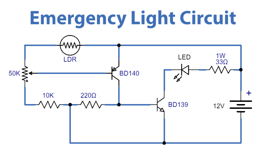
Photoresistors or photoresistors are components that are sensitive to light. It is basically a photocell that works on the principle of light guiding. This passive component is basically a resistor whose resistance value decreases as the light intensity decreases. It's not uncommon for an LDR or photoresistor to have a resistance value of a few megaohms in the dark, then drop to a few hundred ohms in bright light. Hardware Components: You will need the following parts to build this project. 1. Test Board 2. Cable 3. 12V DC 4. Resistor(33ohms) 5. Pot(50k) 6. Low-density lipoprotein 7. BD139npn 8. Bd140npn 9. 5mmLED Description This circuit will turn on a 1 W LED when there is no light on the LDR face. Circuit operation depends on the change of LDR (Light Dependent Resistor) resistance. After completing the circuit, when the LDR is exposed to a sufficient amount of light, its resistance decreases. This then causes the voltage at the base of the PNP transistor to also drop. When the LDR is exposed to a dark environment, its resistance increases, causing the voltage at the base of the PNP transistor to also increase. This voltage acts as a control signal for the BD139 NPN transistor, which triggers the output LED connected to a 33Ω 1W resistor. The control signal at the bottom of the PNP transistor can be tuned using a 50K potentiometer. Application Used as an emergency backup for security systems and industrial sites. It can be used as an emergency light in both home and office settings. It can be used in study rooms and workplaces to avoid sudden power outages. Please refer to the attached project circuit diagram
-
The light comes on when my washer is turned on. But it goes off after a while. There is no response when pressing the power button. After waiting for a few minutes, I heard the washing machine beeping. At this time, the power-on indicator light is on again. After a minute or two it goes off again. After a while, it can be turned on again, and the process is repeated. Check the machine, suspect that there is a problem with the main control board in the lower part of the machine, and dig out the circuit board. Found that there is no 5V output. It is suspected to be a problem with the power block Tny276. I don't have a replacement of the same model on hand. I used tny177 to go up. It can also be turned on. Not extinguished. I don't know if it will last long. Do I need to buy an original model and replace it?
-
I need to replace a PNP BD140 (BD140 datasheet) as I'm restoring a power supply, however the replacement component has its base directly connected to the V+ via the diode bridge. I'm not sure if this is doable. I assumed the collector or emitter would receive the V+. Powered by an 18-volt source, a 100-volt transistor My suggestion is to connect the transistor "upside down," with the base on top of the pict, biased by some DC from the massive resistor soldered to the two big locations, and the emitter and collector permitting the DC from the power supply to the power amp IC.