


Daini
-
Posts
5 -
Joined
-
Last visited
Content Type
Profiles
Forums
Events
Posts posted by Daini
-
-
Interface Arduino with Node-RED to monitor the Temperature and Humidity on a Webpage
Node-RED is a visual tool for non-programmers to work with the Internet of Things, it can be used to build application fasters and reduce the “go to market” time for IoT products. Node-RED can be used to easily interface hardware devices, APIs, and other online services together in new and interesting ways. Node-RED is an open source IoT tool and has been implemented by the IBM Emerging Technology organization. It is written in JavaScript and works on the NodeJS platform.
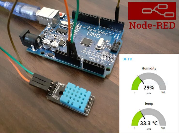
Node-RED operates on module based approach where predefined modules are connected graphically to perform the sequence of operations on Node-RED or in other words it directly accesses data from microcontroller boards like Arduino, Raspberry Pi using the predefined port no. or pin number. In this tutorial, we are going to send DHT11 sensor readings to Node-RED dashboard using Arduino. Similarly, we have also connected Arduino with ThingSpeak to design a weather station.
For this tutorial we will focus only on Arduino and Node-RED. Throughout this tutorial, we will cover how to install and set-up Node-RED on windows. Then we will also design a dashboard on Node-RED and use different input, output and functions nodes to create a flow
Components RequiredHardware components
- Arduino Uno
- DHT11 Sensor
- Jumper Wires
Software apps and online services
- Arduino IDE
- Node.js
- Node-RED
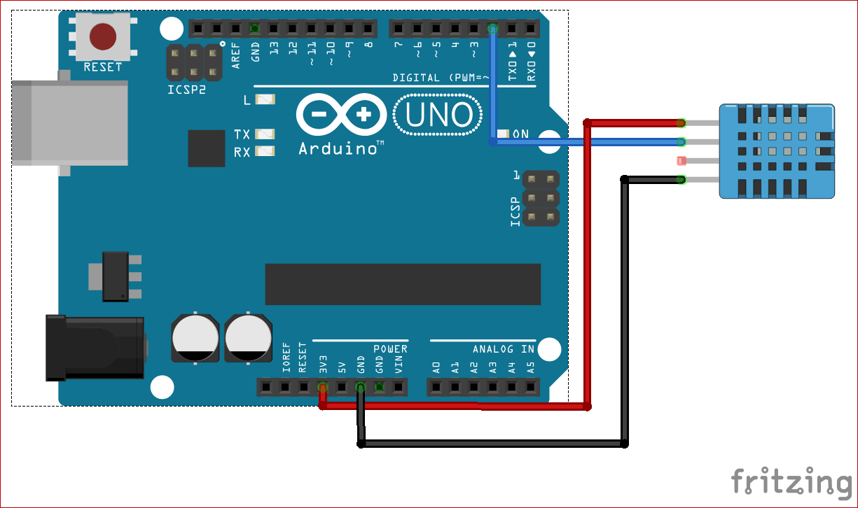
The circuit diagram to interface DHT11 sensor with Arduino is shown below, the schematic was drawn using Fritzing software.

The DHT11 is a popular 3-pin sensor that can measure temperature and humidity. The sensor works with one-wire protocol and is easy to use with development boards like Arduino. The Vcc pin of DHT11 is connected with Arduino’s 3.3v pin, and GND pin is connected with Arduino’s GND pin. While the data pin is connected with 2nd pin of Arduino. Once the connections are done my hardware looked like this
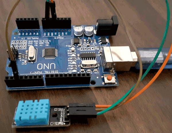
As you can see I have used simple female to male connecting wires to make the connections. The complete set-up is powered by the USB port connected to my computer. We previously connected DHT11 with Arduino to build IOT weather Station.
Code ExplanationComplete program for Arduino Node-RED can be found at the end of this tutorial. Programming Arduino UNO for this project don’t require much effort as it only uses one library for DHT sensor. The Arduino board has to measure the temperature and humidity value from DHT11 sensor and send it out serially using COM port. This serial information will then be processed by the Node-RED.
So start the programming by initializing the required libraries, Arduino pins and variables.
#include <DHT.h>
#define DHTPIN 2     // what pin we're connected to
#define DHTTYPE DHT11   // DHT 11  (AM2302)
DHT dht(DHTPIN, DHTTYPE);
//Variables
int chk;
float hum;  //Stores humidity value
float temp; //Stores temp
String function is used to convert the float variables into string. Here the variable temperature and humidity is converted into string.
String hum1;
String temp1;
In void loop() dht11 sensor calculates the temperature and humidity values and store them into temp and hum variable respectively. Serial print is used to print the temperature and humidity values on serial monitor.
void loop()
{
    //Read data and store it to variables hum and temp
    hum = dht.readHumidity();
    temp= dht.readTemperature();
    hum1 = String(hum);
    temp1 = String(temp);
    //Print temp and humidity values to serial monitor
   // Serial.print("Humidity: ");
    Serial.print(hum1);
    Serial.print(",");
    Serial.print(temp1);
   // Serial.println(" Celsius");

    delay(2000); //Delay 2 sec.
}
Connect the Arduino with the laptop and choose the board and port correctly and then click the Upload button. After uploading the code, open the serial monitor. Make the baud rate of serial monitor as 9600.
Setting up Node-RED1. Install Node.js
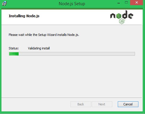
Download the latest version of Node.js from the official Node.js home page. At the time of writing this tutorial the available version was 10.16.0. After downloading run the downloaded MSI file and install Node.js in the default path.
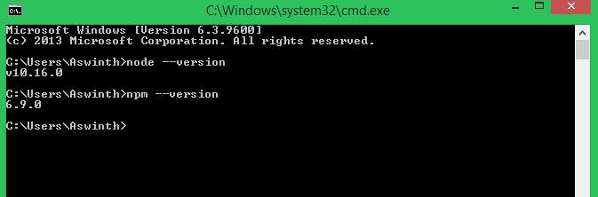
Once installed, open a command prompt and run the following command to ensure Node.js and npm are installed correctly.
node --version
npm --version
You should receive back output with the version number of our package. Mine looked something like this.
2. Install Node-RED
To install Node-RED on your system, run the following command on Command Prompt:
npm install -g --unsafe-perm node-red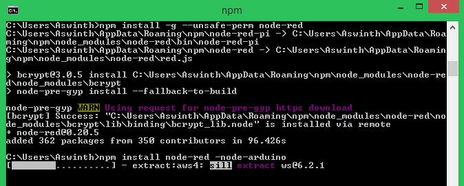
Node-RED doesn’t have preinstalled nodes for Arduino, Serial Port, and Dashboard. So use the following commands to install these nodes:
- To install the Arduino nodes
npm install node-red -node-arduino- To install the serial port node
npm install node-red -node-serialport- To install the Dashboard nodes
npm install node-red -dashboard3. Run Node-RED
Once installed, Run the node red using the following command in the command prompt:
node-red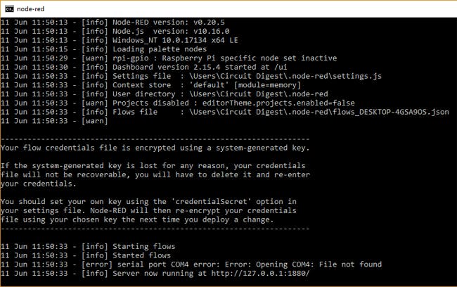
Copy the local-server link to your browser: http://localhost:1880 to access Node-RED. You should see a window like the one below showing node red launch on the desktop.
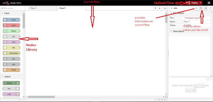
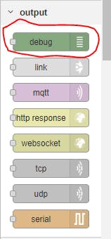
- Node Library is the list of nodes which are representative of hardware, protocols and software features associated with devices
- Current Flow or flow is where the nodes are joined together to create a program
- Debug console works just like the Arduino Serial monitor and can provide the values
- The deploy button is used to upload the flow to target hardware
- The info console provides information on highlighted/selected objects
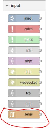
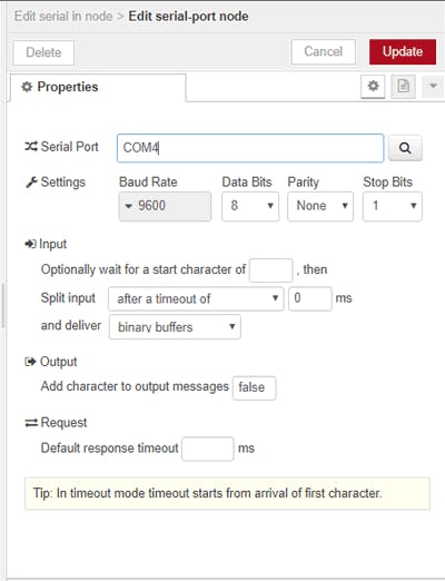
Creating a Flow in Node-REDTo Begin, drag the input Serial node into flow section
Now to edit double click on the node, a pop window will open. In this window enter the serial port at which Arduino is connected and select 9600 in baud rate section.
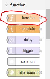
After this scroll down the node palette and drag the two Function node into flow section, one for temperature and other for humidity.
Double click on the first function to enter its name and program.
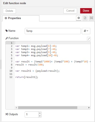
Java code for this function is given below:
var temp1= msg.payload[6]-48;
var temp2= msg.payload[7]-48;
var temp3= msg.payload[9]-48;
var temp4= msg.payload[10]-48;
var result = (temp1*1000)+ (temp2*100) + (temp3*10) + temp4;
result = result/100;
var result1 = {payload:result};
return[result1];
Node-RED receives Humidity and Temperature values in ASCII code format from serial monitor. To display these values on Node-RED Dashboard, we need to convert ASCII code into real values. So to do this above java program is used. In this program every ASCII code is subtracted by 48 except the decimal point and comma.
After Temp function now double click on the second function:
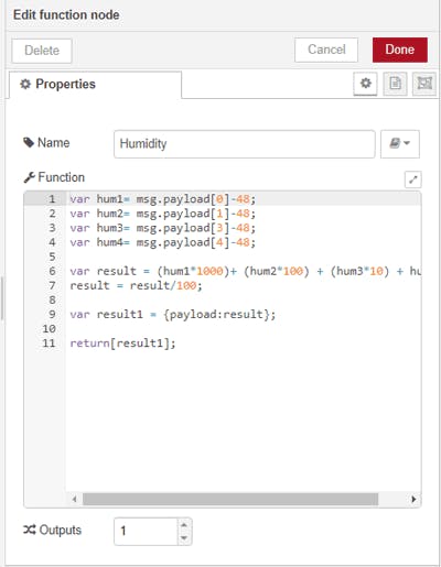
Java code for this function is as follows:
var hum1= msg.payload[0]-48;
var hum2= msg.payload[1]-48;
var hum3= msg.payload[3]-48;
var hum4= msg.payload[4]-48;
var result = (hum1*1000)+ (hum2*100) + (hum3*10) + hum4;
result = result/100;
var result1 = {payload:result};
return[result1];
As explained above this program is used to change the Humidity values from ASCII code format to real values. After completing the temperature and humidity function, scroll down and drag two Debug nodes to flow section.
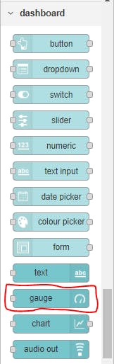
To design the Dashboard, scroll down the node palette to Dashboard and drag two Gauge to flow section for Temperature and humidity.
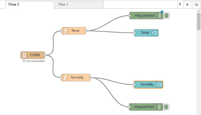
The final flow will look like this
You can directly create this flow on your Node-RED server by importing the following code to your Node-RED server.
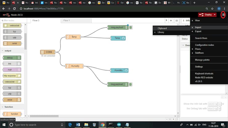
To do this, click on the menu button then Import -> Clipboard. In clipboard, window paste the below-given code.
Node-RED Code
[{"id":"74e0880a.c777f8","type":"tab","label":"Flow 3","disabled":false,"info":""},{"id":"e26c53af.cca2b","type":"serial in","z":"74e0880a.c777f8","name":"","serial":"58430f06.f23e4","x":137.5173568725586,"y":193.7500286102295,"wires":[["e45d22bf.57606","e06252b0.156d2"]]},{"id":"e45d22bf.57606","type":"function","z":"74e0880a.c777f8","name":"Temp","func":"\nvar temp1= msg.payload[6]-48;\nvar temp2= msg.payload[7]-48;\nvar temp3= msg.payload[9]-48;\nvar temp4= msg.payload[10]-48;\n\nvar result = (temp1*1000)+ (temp2*100) + (temp3*10) + temp4; \nresult = result/100;\n\nvar result1 = {payload:result};\n\nreturn[result1];","outputs":1,"noerr":0,"x":307.07645416259766,"y":92.56599521636963,"wires":[["d914ac8d.cd404","9f2a37c9.0d8f88"]]},{"id":"d914ac8d.cd404","type":"debug","z":"74e0880a.c777f8","name":"","active":true,"tosidebar":true,"console":false,"tostatus":false, "complete":"false","x":581.3498992919922,"y":37.79081916809082,"wires":[]},{"id":"e06252b0.156d2","type":"function","z":"74e0880a.c777f8","name":"Humidity","func":"var hum1= msg.payload[0]-48;\nvar hum2= msg.payload[1]-48;\nvar hum3= msg.payload[3]-48;\nvar hum4= msg.payload[4]-48;\n\nvar result = (hum1*1000)+ (hum2*100) + (hum3*10) + hum4; \nresult = result/100;\n\nvar result1 = {payload:result};\n\nreturn[result1];","outputs":1,"noerr":0,"x":315.0911521911621,"y":286.6883945465088,"wires":[["f35a3030.d7841","f7b0f890.f22e18"]]},{"id":"f35a3030.d7841","type":"debug","z":"74e0880a.c777f8","name":"","active":true,"tosidebar":true,"console":false,"tostatus":false, "complete":"false","x":582.6041069030762,"y":361.12417221069336,"wires":[]},{"id":"9f2a37c9.0d8f88","type":"ui_gauge","z":"74e0880a.c777f8","name":"Temp","group":"d5da3e9b.46abf","order":0,"width":0, "height":0,"gtype":"gage","title":"temp","label":"units","format":"{{value}} °C","min":0,"max":"100","colors":["#00b500","#e6e600","#ca3838"],"seg1":"","seg2":"","x":570.0998001098633,"y":99.71789360046387,"wires":[]},{"id":"f7b0f890.f22e18","type":"ui_gauge","z":"74e0880a.c777f8","name":"Humidity","group":"d5da3e9b.46abf","order":1,"width":0, "height":0,"gtype":"gage","title":"Humidity","label":"units","format":"{{value}}%","min":0,"max":"100","colors":["#00b500","#e6e600","#ca3838"],"seg1":"","seg2":"","x":583.8411865234375,"y":288.4635429382324,"wires":[]},{"id":"58430f06.f23e4","type":"serial-port","z":"","serialport":"COM4","serialbaud":"9600","databits":"8","parity":"none","stopbits":"1","waitfor":"","newline":"0","bin":"bin", "out":"time","addchar":"false","responsetimeout":""},{"id":"d5da3e9b.46abf","type":"ui_group","z":"","name":"DHT11","tab":"784aac14.5c2404","order":2,"disp":true,"width":"6", "collapse":false},{"id":"784aac14.5c2404","type":"ui_tab","z":"","name":"Station","icon":"dashboard","order":1,"disabled":false,"hidden":false}]
Now flow is ready to deploy. We can deploy a flow on Node-RED using the deploy button.
To access the Node-RED Dashboard, copy the link: http://localhost:1880/ui in your browser. Node-RED Dashboard will look like this:
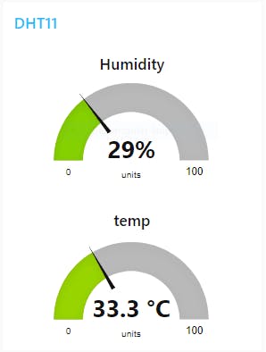
By forwarding the port in your router, this webpage can be accessed from anywhere over the internet. So this is how Node-RED can be used to do graphical programming and used to build IoT based application.
PCB Design Analysis Software. NextDFM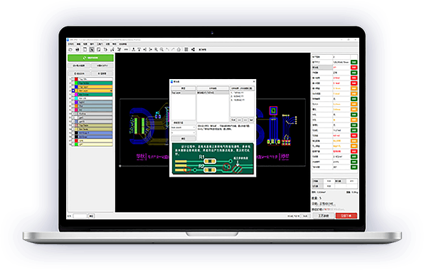
Nextdfm Software
NextDFM is a PCB problem detector and engineering tool by NextPCB, one of the most professional PCB manufacturers in the world based in China. NextDFM is a simple software which can be learnt easily by a non regular PCB designer also. The UI created by them is very simple and PCB design analysis can be done in just a few clicks.
Help you quickly familiarize DFM design specifications and production needs to determine whether there are any manufacturing constraints
Schematics
Circuit
Code
Code
Arduino#include <DHT.h> //Constants #define DHTPIN 2 // what pin we're connected to #define DHTTYPE DHT11 // DHT 11 (AM2302) // Initialize DHT sensor for normal 16mhz Arduino DHT dht(DHTPIN, DHTTYPE); //Variables int chk; float hum; //Stores humidity value float temp; //Stores temperature value void setup() { Serial.begin(9600); dht.begin(); } String hum1; String temp1; void loop() { //Read data and store it to variables hum and temp hum = dht.readHumidity(); temp= dht.readTemperature(); hum1 = String(hum); temp1 = String(temp); //Print temp and humidity values to serial monitor // Serial.print("Humidity: "); Serial.print(hum1); Serial.print(","); Serial.print(temp1); // Serial.println(" Celsius"); delay(2000); //Delay 2 sec. }
-
Jzkzj
-
Components Used1 NodeMCU
NodeMCU is an open source firmware for which open source prototyping board designs are available
1 RelayLoad : 10A, AC 250V/ 15A, 125V
1 Bulb
Google assistant is AI (Artificial Intelligence) based voice command service. Using voice, we can interact with google assistant and it can search on internet, schedule events, set alarms, control appliances, etc.
This service is available on smartphones and Google Home devices.
We can control smart home devices including lights, switches, fans and thermostats using our Google Assistant.
I build an application which can control home appliances. Here, I control 60 W bulb using Google Assistant service.
This application includes Google assistant along with Adafruit server and IFTTT service.
Hardware Used
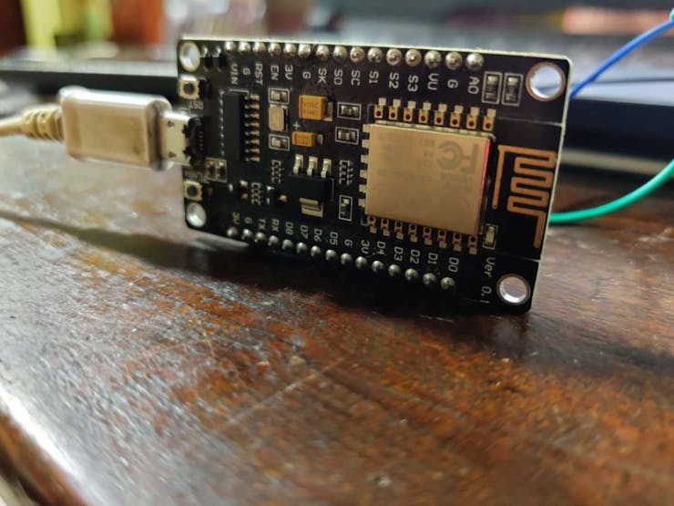
- NodeMCU – 32-bit ESP8266 development board with Wi-Fi SoC.
- Relay module
- One 60 W Bulb
To build home automation application, I used three different platforms
- Google Assistant
- Adafruit
- IFTTT
To use above services we need to configure them.
High Quality PCBs From NEXTPCB
Nextpcb is one of the best Online PCB manufacturing company from where you can order PCBs online without any hassle. The company works 24 hours a day, 7 days a week nonstop. With their high tech machinery and automated work stream, they can manufacture huge quantities of high-class PCBs within hours.
NEXTPCB can develop PCBs of various complexity. They develop Simple and cheap PCBs with Single layer board for hobbyists and enthusiasts as well as complex multi layer board for high standard industrial applications. Nextpcb works with large product manufacturers and may be the PCB of devices you are using such as laptop or mobile phones were made at this factory
Adafruit
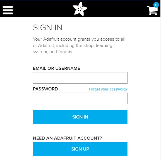
First, created account at www.Adafruit.io
Now, create dashboard at Adafruit. This dashboard is a user interface to control things remotely.
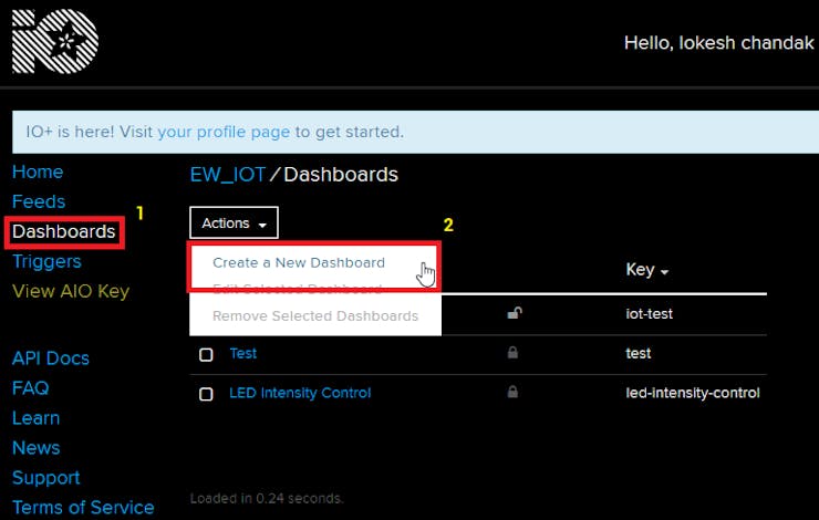
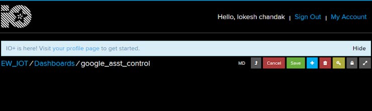
After following above steps, provide name to the dashboard and save it. We can see our dashboard as follows,
Now, create feed (user interface) to control light On-Off. To create it, just click on ‘+’ symbol and select toggle feed shown below,
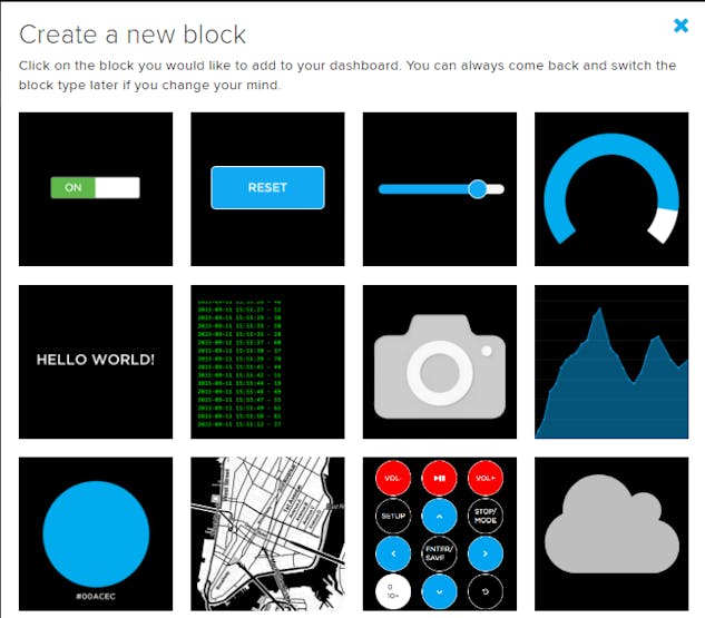
After selecting toggle feed, pop-up window appears as shown below.
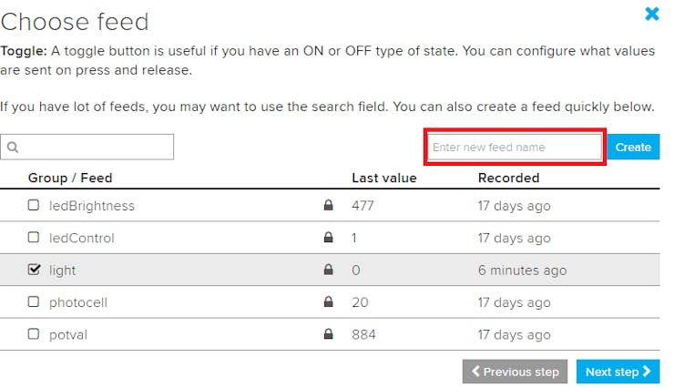
Enter name of our feed (shown in red box) and create it. After creation, select the created feed (here mine is light) and then click on Next step.
In the next step configure the feed which is shown below,
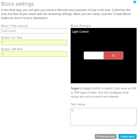
Here, I used 0(OFF) and 1(ON) text for button and then click on create. This will create toggle button on your dashboard which can be used to control things remotely.
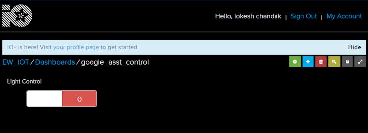
Now, my dashboard is ready for IoT application like home automation.
IFTTT (If This Then That)
If This Then That, also known as IFTTT is a free web-based service to create chains of simple conditional statements, called applets. An applet is triggered by changes that occur within other web services such as Gmail, Facebook, Telegram, Instagram, or Pinterest.
For example, an applet may send an e-mail message if the user tweets using a hashtag or copy a photo on Facebook to a user's archive if someone tags a user in a photo.
Here, I used IFTTT to use google assistant service and Adafruit service in chain. So, when I use google assistant to control light of my home by saying Ok google, turn the light ON or OFF. Then IFTTT interpret the message and can send it to Adafruit’s dashboard as a understandable command to the created feed.
Configure IFTTT
First step is creating account on IFTTT.

Note: Create account on IFTTT byusing same e-mail id which you have used for Adafruit.
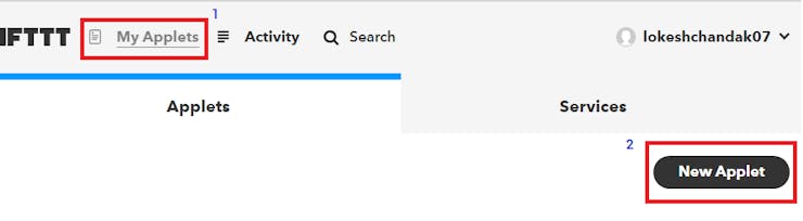
After account creation, click on My Applets and then select New Applet shown below,
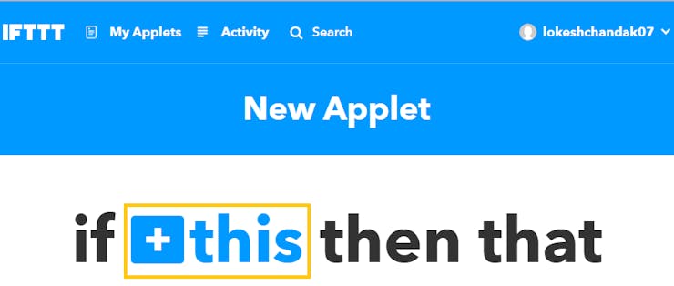
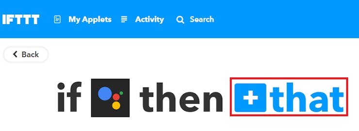
After selecting a new applet, we get a new page in which we should click on to This as shown in below image.
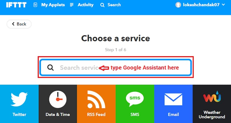
Then search for Google Assistant and select it.
Now, enter voice phrases which we will use as a command for google assistant.
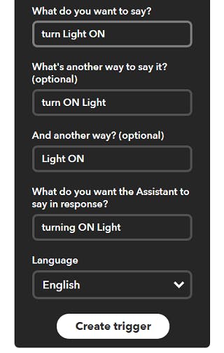
We can enter any phrase as per our application. As you can see, the phrases entered in the above fields is for making Light ON. For making Light OFF, we have to create another applet with different phrases.
Now, we get another page on which we have to click on that option which is used to connect Google Assistant with Adafruit.
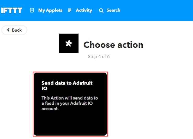
Then search for Adafruit and select it.

After selecting Adafruit, choose action as shown below,
Now enter what data we need to send to which feed of Adafruit dashboard.
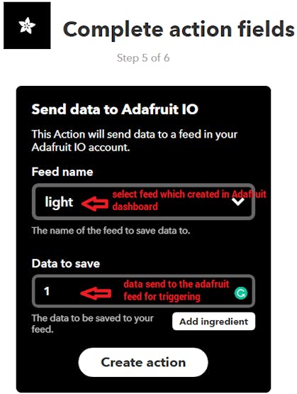
Click on Create Action.
So, when I use Google Assistant on my mobile and give voice command as “Ok Google, Turn LED ON”, applet created in IFTTT receive this command and will send data ‘1’ to the Adafruit feed. This will trigger the event on Adafruit dashboard which is continuously monitored by the microcontroller (here NodeMCU). This microcontroller will take action as per the data change on the Adafruit dashboard.
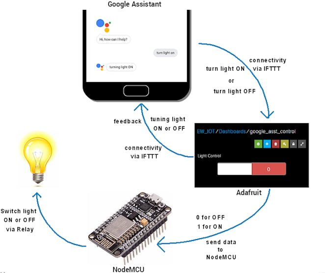
Interfacing Diagram
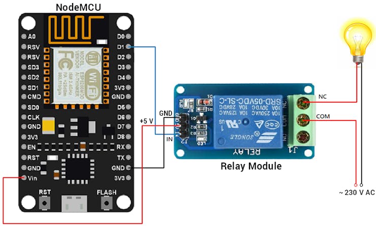
Circuit Diagram for Home Appliance Control using google Assistant
Library
Here, I used the Adafruit MQTT library for receiving data from the Adafruit server. To install this library, select option Sketch -> Include Library -> Manage Libraries.
In that library, search for Adafruit MQTT and installed it.
Control Home’s Light using Google Assistant and NodeMCU
I build an IoT based home automation application in which I control the 60 W bulb at remotely using AI based Google Assistant.
Here, I used NodeMCU to read data from Adafruit server and act accordingly. 60 W bulb connected to NodeMCU via relay for controlling it voice command using google assistant.
High Quality PCBs From NEXTPCB Nextpcb Is one of the best Online PCB manufacturing Company from where you can order PCBs online without any hassle. The company fast lead time : as fast as 24 hours. With their high tech machinery and automated work stream, they can manufacture huge quantities of high-class PCBs within hours.Nextpcb can Develop PCBs of various complexity . They Develop simple and cheap PCBs with single layer Board For hobbyists and enthusiasts as well as complex multi layer board for high standard industrial applications NextPcb work with Large product Manufacturers And may Be the PCB of devices you are using such as laptop or smartphone were made at this factory.
High Quality PCBs From NEXTPCB
 Nextpcb PCB Sample
Nextpcb Is one of the best Online PCB manufacturing Company from where you can order PCBs online without any hassle. The company fast lead time : as fast as 24 hours. With their high tech machinery and automated work stream, they can manufacture huge quantities of high-class PCBs within hours.
Nextpcb can Develop PCBs of various complexity . They Develop simple and cheap PCBs with single layer Board For hobbyists and enthusiasts as well as complex multi layer board for high standard industrial applications NextPcb work with Large product Manufacturers And may Be the PCB of devices you are using such as laptop or smartphone were made at this factory.
-
Hii Maker's
Today we will make Emergency Neighbour notifier Using GSM 900l
The stuff needed to make it
Arduino Uno
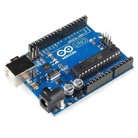 Arduino uno
Gsm Module
GSM module Sim900A
A GSM module or a GPRS module is a chip or circuit that will be used to establish communication between a mobile device or a computing machine and a GSM or GPRS system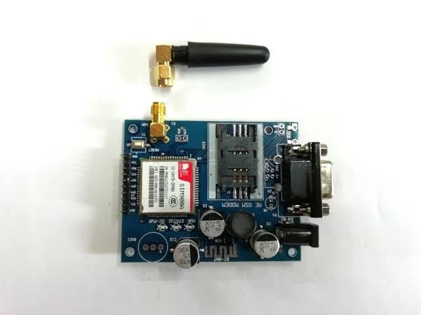
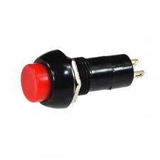
Push switch
A Push Button switch
is a type of
switch
which consists of a simple electric mechanism or air
switch
epending on model they could operate with momentary or latching action function. ...
A Push Button switch is a type of switch which consists of a simple electric mechanism or air switch mechanism to turn something on or off. Depending on model they could operate with momentary or latching action function. ...
Arduino, GSM module and a simple push button and other components this project is possible. The mobile number and Emergency alert message is pre-defined and stored in the Arduino. When the push button in pressed Emergency Alert message is sent to the respective numbers. ..
Those who are living alone and are in an Emergency situation like
Low Blood Sugar(Hypoglycemia)
Chest Pain/Heart Attack
Major Cuts
Strokes
Choking etc. 1 / 3
1 / 32. Theft situation/Intruder
Code :-
int state = 0;
const int pin = 9;
void setup()
{
Serial.begin(9600);
}
void loop()
{
if (digitalRead(pin) == HIGH && state == 0) {
Serial.print("\r");
delay(100);
Serial.print("AT+CMGF=1\r");
delay(100);
Serial.print("AT+CMGS=\"+aabbbbbbbbbb\"\r");
Serial.print("AT+CMGS=\"+aacccccccccc\"\r");
Serial.print("AT+CMGS=\"+aacccccccccc\"\r");//International no.
delay(100);
Serial.print("HELP,Flat No 201-A");//Emergeny message
delay(100);
Serial.write(0x1A);
delay(100);
state = 1;
}
if (digitalRead(pin) == LOW && state == 1) {
state = 0;
}
}High Quality PCBs From NEXTPCB
Nextpcb Is one of the best Online PCB manufacturing Company from where you can order PCBs online without any hassle. The company fast lead time : as fast as 24 hours. With their high tech machinery and automated work stream, they can manufacture huge quantities of high-class PCBs within hours.Nextpcb can Develop PCBs of various complexity . They Develop simple and cheap PCBs with single layer Board For hobbyists and enthusiasts as well as complex multi layer board for high standard industrial applications NextPcb work with Large product Manufacturers And may Be the PCB of devices you are using such as laptop or smartphone were made at this factory.High Quality PCBs From NEXTPCB
Nextpcb PCB SampleNextpcb Is one of the best Online PCB manufacturing Company from where you can order PCBs online without any hassle. The company fast lead time : as fast as 24 hours. With their high tech machinery and automated work stream, they can manufacture huge quantities of high-class PCBs within hours.
Nextpcb can Develop PCBs of various complexity . They Develop simple and cheap PCBs with single layer Board For hobbyists and enthusiasts as well as complex multi layer board for high standard industrial applications NextPcb work with Large product Manufacturers And may Be the PCB of devices you are using such as laptop or smartphone were made at this factory.
Code
IoT Wireless Weather Station using Arduino
in Electronic Projects
Posted
Story
Global warming has lead to unpredictable climates; researchers around the world are using weather stations to observe record and analyse weather patterns to study climate changes and provide weather forecasts. These Weather stations normally comprises of few sensor to measure environmental parameters and a monitoring or logging system to analyze these parameters. In this tutorial we will learn how to build such a wireless IoT based weather station which can measure critical environmental parameters like Temperature, Humidity and Pressure. Also since our weather station is IoT enabled, we can send these parameters to a ThingSpeak channel (IoT cloud) where we can store, analyse and access the data remotely. weather station using Raspberry Pi earlier, which is pretty much similar to this project.
We will be using he Arduino board along with DHT11 sensor, BMP180 sensor and ESP8266 wifi module. The DHT11 sensor senses the temperature and humidity, while BMP180 sensor calculates the pressure and ESP8266 is used for internet connectivity. In our previous project, we already learnt to use the DHT11 sensor to monitor temperature and humidity with Arduino, here in this project, we are adding another sensor (BMP180) to make a complete weather station using Arduino. Sending these data to ThingSpeak enables live monitoring from anywhere in the world and we can also view the logged data which will be stored on their website and even graph it over time to analyze it.
Components Required
Circuit DiagramThe complete circuit for Arduino based IoT Weather Station is shown below.
The DHT11 sensor is powered by the 5V pin of the Arduino and its data pin is connected to pin 5 for one wire communication. The BMP180 sensor is powered by the 3.3V pin of Arduino and its data pins SCL (Serial Clock) and SDA (Serial Data) are connected to A4 and A5 pin of Arduino for I2C communication.
The ESP8266 module is also powered by the 3.3V pin of the Arduino and its Tx and Rx pins are connected to Digital pins 2 and 3 of Arduino for serial communication. You can use the below table as reference for making your connections.
ThingSpeak is an open data platform that allows you to aggregate, visualize, and analyze live data in the cloud. You can control your devices using ThingSpeak, you can send data to ThingSpeak from your devices, and even you can create instant visualizations of live data, and send alerts using web services like Twitter and Twilio. ThingSpeak has integrated support from the numerical computing software MATLAB. MATLAB allows ThingSpeak users to write and execute MATLAB code to perform preprocessing, visualizations, and analyses. ThingSpeak takes minimum of 15 seconds to update your readings. We have also done other interesting projects with ThingSpeak like
Step 1: ThingSpeak Account SetupTo create channel on ThingSpeak first you need to Sign up on ThingSpeak. In case if you already have an account on ThingSpeak, sign in using your id and password.
For creating your account go to www.thinspeak.com
Click on Sing up if you don’t have an account and if you already have an account click on sign in. After clicking on signup fill your details.
After this verify your E-mail id and click on continue.
Step 2: Create a Channel for Your DataOnce you Sign in after your account verification, Create a new channel by clicking the “New Channel” button
After clicking on “New Channel,” enter the Name and Description of the data you want to upload on this channel.
Enter the name of your data ‘Humidity’ in Field1, ‘Temp’ in Field2 and ‘Pressure’ in Field3. If you want to use more Fields you can check the box next to Field option and enter the name and description of your data.
After this click on save channel button to save your details.
Step 3: API KeyTo send data to ThingSpeak, we need a unique API key, which we will use later in our code to upload our sensor data to Thingspeak Website.
Click on “API Keys” button to get your unique API key for uploading your sensor data.
Now copy your “Write API Key.” We will use this API key in our code.
Code Explanation
Programming part plays a very important role to perform all the operations in a project. As usual complete code is given at the end. Start the code by including all the required libraries and defining all the variables.
After this enter the WiFi name, password of your Wi-Fi router and then also enter the API key that you copied from the ThingSpeak channel.
In void setup() function it connects with the Wi-Fi and starts the BMP180 and DHT11 sensor.
Using void Transmission() function we calculate the temperature, humidity and pressure using the BMP180 and DHT11 sensor.
These commands are used to connect with ThingSpeak server and then print the temperature, humidity and pressure values in different fields.
Running the IoT Arduino Weather StationNow Connect the Arduino with the laptop and choose the board and port correctly and then click the Upload button. After uploading the code, open the serial monitor. Make the baud rate of serial monitor as 9600. You will see your Wi-Fi Id, password and temperature, humidity and pressure values on serial monitor.
Now navigate to the ThingSpeak channel and check your channel, you will see the temperature, humidity and pressure values like shown in the below graphs.
This is how you can build Arduino Weather Station where the temperature, humidity and pressure can be monitored from anywhere in world over the internet.
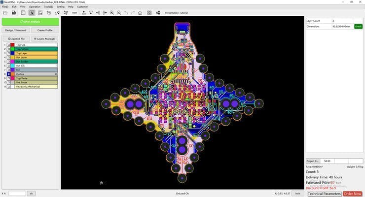
PCB Design Analysis Software. NextDFMNextdfm Software
NextDFM is a PCB problem detector and engineering tool by NextPCB, one of the most professional PCB manufacturers in the world based in China. NextDFM is a simple software which can be learnt easily by a non regular PCB designer also. The UI created by them is very simple and PCB design analysis can be done in just a few clicks.
Download Software
Help you quickly familiarize DFM design specifications and production needs to determine whether there are any manufacturing constraints
Schematics
Circuit
Code
Code
Arduino