


Maydori
-
Posts
3 -
Joined
-
Last visited
-
Days Won
1
Content Type
Profiles
Forums
Events
Posts posted by Maydori
-
-
Hello,
Recently I am trying to use TPS7A3001(datasheet) for providing clean and stable +5 and -5 V power for my PCBs. I am aware that the output voltage is adjustable by changing the values of external resistors which is connected between the OUT pin and GND. After reading the datasheet, I have some questions:
1, Basically I know one rule is that the current should be greater than 5 uA. But is there any criteria for selecting proper values of resistors? e.g. I can choose two resistors of 10 K and 20 K or 100 K and 200 K to get the same desired voltage, what is the difference between these two selections?
2, In the datasheet of these two devices, I found: it is recommended that the board be designed with separate ground planes for IN and OUT, with each ground plane connected only at the GND pin of the device.
While in the datasheet of the evaluation module TPS7A30-49EVM-567, I found the ground planes of IN and OUT are not separate from each other.
I am wondering which rule I should obey when designing my PCBs? And why?
Much thanks in advance.
-
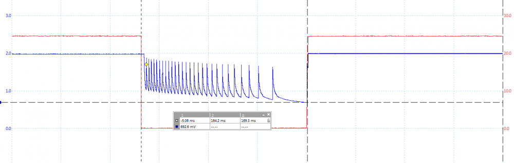
'm using STM32L0 which was from http://www.kynix.com/Detail/1118455/STM32L062K8T6.html. My firmware operates at 2V. These are stepped down from 24V. If I have a short of the 24V for a short period of time this causes a brown out on my 2V the voltage begins to oscillate from my step down.
I want to solve this with software.
If seen that I don't get this problem without a load ( while(1), all peripherals turned off. )
I added a for-loop at the start of the program, that held for a few seconds, that didn't help. To me this means the program does not actually reset. Its somehow latches up unless the voltage drops bellow a threshold.
Can I use under voltage detection or brown out detection of STM to prevent this?
I need to force a reset as soon as the voltage drops bellow around 1.8V. I need to react, if I don't want an oscillation, within around 3ms.

DIY A Portable Speaker by Yourself
in Electronic Projects
Posted
Today I want to share a project of making a portable speaker.
You all have seen portable speakers becominng popular these days but most of them are quite expensive so I am going to show you how to make you own portable speakers with minimum parts. It will only takes 1 hours to make and test , and it can run on any usual usb charger. SO, lets get started!
Step 1: Getting parts and tools
Parts required
Tools required
Step 2: Understanding the circuit
The circuit is very simple just hook up two wires to the vcc 5V and ground pin of the amplifier ic
connect one speaker to the one channel output name +L -L and other to +R -R, these are the output to our speakers
TO connect input to the amplifier,strip off a aux cable from one side and carefully strip 3 signel wires, to check which wire is ground put the multimer on continuit mode and attact one lead to ground pin and other to 3 wires one by one, the wire which will produce a sound is the ground wire
Now carefully solder the wire to the ground input point and other to left and right channel inputs( attach any input pin to either left channel or right channel input it doesn't matter)
Now our circuit is complete so test it using a 5v dc supply to input and playing music
if everything works fine then its time to asse,ble th
Step 3: Soldering components together
Solder the components according to the described schematic
Step 4: Putting circuit in a casing
In my case the speaker case itself serve as a casing for my speaker. You can also use a diff casign for your speaker. It all depends on how you use it but the concept remains the same.
After soldering the circuit put all the contents carefully into the casing and glue it using glue gun or use my way using a hot glue stick and soldering iron( always remember to clean solder immediately after using hot glue stick)
Step 5: Adding power supply
You can use tis circuit directly with any standard 5v supply or by using a microusb female adapter(like i did).
I salavaged a micro usb female jack from a old powerbank and ued its casing for protective casing of the female jack ( as it is very fragile)
to salavage a old powerbank circuit simply remove the battery and put +ve wire on the positive end of the battery connector of powerbank and -ve to the negative end of the battery. I have removed the battery to save some space
Step 6: Close the casing
now safey close the casing of your speaker and if possible use screw to close your casing as it is easier in the future if their will be any problem
Step 7: Testing time
Now to test your creation plug the power suplly and attach AUX cable to your phone/ipod etc and see if it works.![]() then please feel free to ask in comment section.
then please feel free to ask in comment section.
If you have any QUESTIONS OR SUGGESTION