Today I want to share a project of making a portable speaker.
You all have seen portable speakers becominng popular these days but most of them are quite expensive so I am going to show you how to make you own portable speakers with minimum parts. It will only takes 1 hours to make and test , and it can run on any usual usb charger. SO, lets get started! Step 1: Getting parts and tools
Parts required
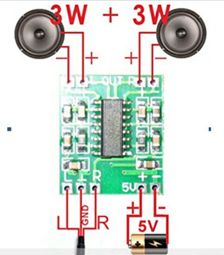
A Amplifier circuit/op amp circuit ( I used a PAM8403 class D 2-channel amplifier circuit, you can buy it here :http://www.kynix.com/Detail/647721/PAM8403.html.)
A project casing or a old speaker with space inside to put circuit
A aux cable
some wires
a micro usb adapter ( if you want to use play it using regular charger)
regular usb cable
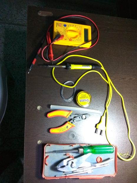
Tools required
soldering iron
soldering wire
hot glue stick
Step 2: Understanding the circuit
The circuit is very simple just hook up two wires to the vcc 5V and ground pin of the amplifier ic
connect one speaker to the one channel output name +L -L and other to +R -R, these are the output to our speakers
TO connect input to the amplifier,strip off a aux cable from one side and carefully strip 3 signel wires, to check which wire is ground put the multimer on continuit mode and attact one lead to ground pin and other to 3 wires one by one, the wire which will produce a sound is the ground wire
Now carefully solder the wire to the ground input point and other to left and right channel inputs( attach any input pin to either left channel or right channel input it doesn't matter)
Now our circuit is complete so test it using a 5v dc supply to input and playing music
if everything works fine then its time to asse,ble th
Step 3: Soldering components together
Solder the components according to the described schematic
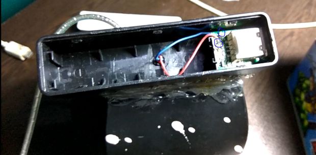
Step 4: Putting circuit in a casing
In my case the speaker case itself serve as a casing for my speaker. You can also use a diff casign for your speaker. It all depends on how you use it but the concept remains the same.
After soldering the circuit put all the contents carefully into the casing and glue it using glue gun or use my way using a hot glue stick and soldering iron( always remember to clean solder immediately after using hot glue stick)
Step 5: Adding power supply
You can use tis circuit directly with any standard 5v supply or by using a microusb female adapter(like i did).
I salavaged a micro usb female jack from a old powerbank and ued its casing for protective casing of the female jack ( as it is very fragile)
to salavage a old powerbank circuit simply remove the battery and put +ve wire on the positive end of the battery connector of powerbank and -ve to the negative end of the battery. I have removed the battery to save some space
Step 6: Close the casing
now safey close the casing of your speaker and if possible use screw to close your casing as it is easier in the future if their will be any problem
Step 7: Testing time
Now to test your creation plug the power suplly and attach AUX cable to your phone/ipod etc and see if it works.
If you have any QUESTIONS OR SUGGESTION then please feel free to ask in comment section.